
|
projectclifford repositoryclifford_lcd clifford_sim_1 left_leg_demo_new servo_driver teleop_controller ultrasonic |
|
|
Repository Summary
| Description | Quadruped Robotic Dog 🐶 based on Boston Dynamic's Spot. Controlled through a PS4 controller. With Raspberry Pi 4B as the brain 🧠. |
| Checkout URI | https://github.com/msalaz03/projectclifford.git |
| VCS Type | git |
| VCS Version | master |
| Last Updated | 2025-01-02 |
| Dev Status | UNMAINTAINED |
| CI status | No Continuous Integration |
| Released | UNRELEASED |
| Tags | No category tags. |
| Contributing |
Help Wanted (0)
Good First Issues (0) Pull Requests to Review (0) |
Packages
| Name | Version |
|---|---|
| clifford_lcd | 0.0.0 |
| clifford_sim_1 | 0.0.0 |
| left_leg_demo_new | 0.0.0 |
| servo_driver | 0.0.0 |
| teleop_controller | 0.0.0 |
| ultrasonic | 0.0.0 |
README
Project Clifford
Overview (Please Read)
Over the past four months Cameron, Chase and I tried tackling our version of Boston Dynamic’s Spot. This repository contains the source code that interfaces all hardware interactions between our small red friend. The software includes prebuilt libraries designed for the Raspberry Pi and also references other projects similar to ours.
Now then, running on Ubuntu 22.04 LTS using ROS-Humble we went through a series of processes to organize this into a simple manner. However, we will note that they’re some poor practices as a result of time constraints and it is our first time working with the ROS framework. These will be noted and clarified further in this document. Clifford is an entirely 3D-printed project that uses inverse kinematics to simulate a dog walking. Clifford also has an FPV camera mounted which can be accessed through any web browser provided you’re on the same network as him.
Please check the references, this would have not been possible without open-source projects.
Video Demo:
https://youtube.com/shorts/WbrB4VmLomk?feature=share
Setup
The organization of nodes is not ideal. However, with time it can be reorganized neatly. Currently, we have mostly everything inside a single node. For anyone attempting to recreate anything similar please take the time to do so before programming the entire project.
Three most important folders for this project.

projectclifford_ws/
│
├── src/
│   ├── clifford_sim_1
│   │   └── ...
│   ├── servo_driver
│   │   └── ...
│   └── ...
│   ├── teleop_controller
│   │   └── ...
│   └── ...
For Using RVIZ With Clifford
To test our kinematic equations more efficiently we used RVIZ to visualize what is happening when there is a controller input. ‘clifford_sim_1’ contains a URDF file for the final version of Clifford, exported through SolidWorks URDF exporter. The launch file within this directory only launches the URDF file into RVIZ and does not contain RobotStatePublisher by default. You can enable joint-state-publisher-gui by uncommenting the related lines within the launch file or can use an additional launch file that waits for joy (controller input) and joint-state-publisher topic. The second directory relative to running RVIZ is ‘teleop_controller’ which creates a topic for joint-state-publisher.
NOTE: This totally could have been organized into a single launch file but wasn’t due to circumstances at the time.
In order to launch please do the following.
ros2 launch clifford_sim_1 clifford_sim_1.launch.py
ros2 launch teleop_controller Clifford_full_model.launch.py
For Launching and Booting Clifford
To physically launch Clifford is pretty simple (as long as you have all required dependecies), simply run the following command.
Note: At this point Clifford cannot physically turn as the turning motion was not programmed, however the kinematic equations needed to do are solved and within the software.
ros2 launch servo_driver joy_servos.launch.py
If you want don’t want to follow Clifford, you can see where he is through livestreamed footage. First identify the IPV4 address of clifford and type the following.
xxx.xxx.xxx.xxx:8081
Hardware
From researching similar projects to Clifford and our testing we sourced components that we thought were optimal for this project, consisting of two voltage regulators to isolate the power going into the servo driver and Raspberry Pi. An ADC board to measure different voltage levels into a relative percentage for battery life. A high-capacity battery to prolong battery life. LCD screen to demonstrate battery life in real time. 25 KG servos, a mixture of torque and speed to ensure smooth movements.
| Electrical Component | Model Name |
| Controller | Raspberry Pi 4B |
| Camera | Arducam 16MP Wide Angle USB Camera |
| Voltage Regulator for Pi | LM2596 |
| Voltage Regulator for Servos | DROK DC-DC High Power |
| LiPo Battery | Zeee 2S LiPo 6200mAh @ 7.4V |
| Servos | DS3225MG |
| Servo Driver | PCA9685 |
| ADC Board | ADS1115 |
| Gyroscope | MPU-6050 |
| LCD 16x2 | Sunfounder LCD1602 16x2 |
Communication Protocol
As we were using multiple third-party modules such as servo driver we utilized the I2C bus provided on the Raspberry Pi 4B. This worked perfectly but didn’t allow us to have multiple devices using I2C, as we had a few more. Creating a simple PCB using header pins we created an I2C bus expander that allowed all devices to meet at a single point to communicate with the Pi.
FPV Camera
Using motion libraries we were able to set up a first-person live-streaming feed on a local network. By dedicating a specified port to live-streaming (8081) simply use the IPV4 address followed by the port like so xxx.xxx.xxx.xxx:8081 to access from any device on the same network. To set the config file for the motion service to work navigate to:
sudo nano /etc/default/motion
Make the following changes to the config file:
daemon on
stream_localhost off
webcontrol_localhost off
framerate 1500
stream_quality 100
quality 100
width 640
height 480
post_capture = 5
After that navigate to the default file:
sudo nano /etc/default/motion
Make sure the file contains the following if you want live streaming to start when turning on the Pi.
start_motion_daemon=yes
Calculating Battery Life
Using the 5V pin provided to power the ADS1150, we needed to step down the balance charger voltage outputted from the LiPo. We created a small PCB board that included a voltage divider circuit such that the highest voltage read would be ~5V. Now with voltage being able to be read, we then determined the highest voltage ie @ 100% and at 0%. We then used the current voltage to calculate the current battery percentage.
Other Useful Components
After finalizing the project here our somethings that help improve production.
- Buy a dedicated LiPo Battery Balance Charger, these will guarantee the quality of battery being used and can charge relatively quick.
- Using a DC Power Supply, would prevent the need of constantly recharging the battery after testing.
- If possible maximize the hardware you use. We settled on the Raspberry Pi 4B, it was okay. I figured I would do most of my programming on the Pi anyway but there were times it was just so slow.
- Get a dedicated cooler for your controller, especially for the Raspberry Pi. These things will heat up quickly.
Software
The software went through many revisions, currently, all software is under a single node, ‘servo2_pca9685’ within the directory ‘servo_driver’. This includes the various kinematic equations needed to move each leg. The ultrasonic sensor can also be found within this file to override a controller input if Clifford detects he is too close to an object.
PS4 Joystick
Using the left joystick, you can determine the direction of movement (forward or backward). This is handled through flags that check the joy topic axes sign (-/+). Using the Joy topic callback we can constantly update Clifford’s relative position. Clifford’s walking consists of a 4-point leg motion. However, the legs move in pairs, meaning the front left and back right move together, and the front right and back left move together. The overall structure of the walking gait was as follows, a single set will take ‘charge’ meaning they’re the legs move forward while the others are dragging backward creating the ability to go forward. The speed at which the legs drag backward is based on the input of the user, and timing so that a pair of legs complete a single point (the ones dragging backward) while the other completes three 3 (the other set). This allows us to constantly have two points of contact with the ground at all times.
The leg motion follows a square pattern, making the programming straightforward. At each position, the program checks whether the leg is moving forward or backward and its current relative position (x, y, z). Only one coordinate (either x or y) changes at a time. Multiple conditions verify if the leg has passed or reached its target coordinate, then update the target and current indices. While most of the programming remains consistent, the conditions for each leg differ slightly.
Sample Code
     if forward and self.front_right_current[2] >= self.front_right_target[self.set1_target_index][2] or \
                        (not forward and self.front_right_current[2] <= self.front_right_target[3][2]):
                            self.update_servos()
                    else:
                        if forward:
                            self.front_right_current[2] = self.front_right_target[self.set1_target_index][2]
                            self.back_left_current[2] = self.back_left_target[self.set1_target_index][2]

                            self.set1_target_index = 2
                            self.set1_walk_index = 1
                        else:
                            self.front_right_current[2] = self.front_right_target[self.set1_walk_index][2]
                            self.back_left_current[2] = self.back_left_target[self.set1_walk_index][2]
                            self.set1_walk_index = 3
                            self.set1_target_index = 0

                        if not forward:
                            self.front_left_current[0] = self.front_left_target[self.set2_walk_index][0]
                            self.back_right_current[0] = self.back_right_target[self.set2_walk_index][0]
                            self.set2_walk_index = 3
                            self.set2_target_index = 0
PS4 Buttons
Various buttons are configured for the following. During this time it changes a flag so that clifford knows that he is no longer waiting for ‘walk’ commands. Additionally, for any third party expanders
- Lay down or stand tall.
- Lean side to side.
- Lean forward and backward.
- Reset to default stance.
- Shutdown Clifford.
LCD Node
We were unable to access the libraries outside their installation location, so creating a node with the LCD running via the launch file didn’t work. Instead, we created a separate Python script to run in parallel with the Clifford launch. Ideally, we would import the libraries into a dedicated node.
Inverse Kinematics
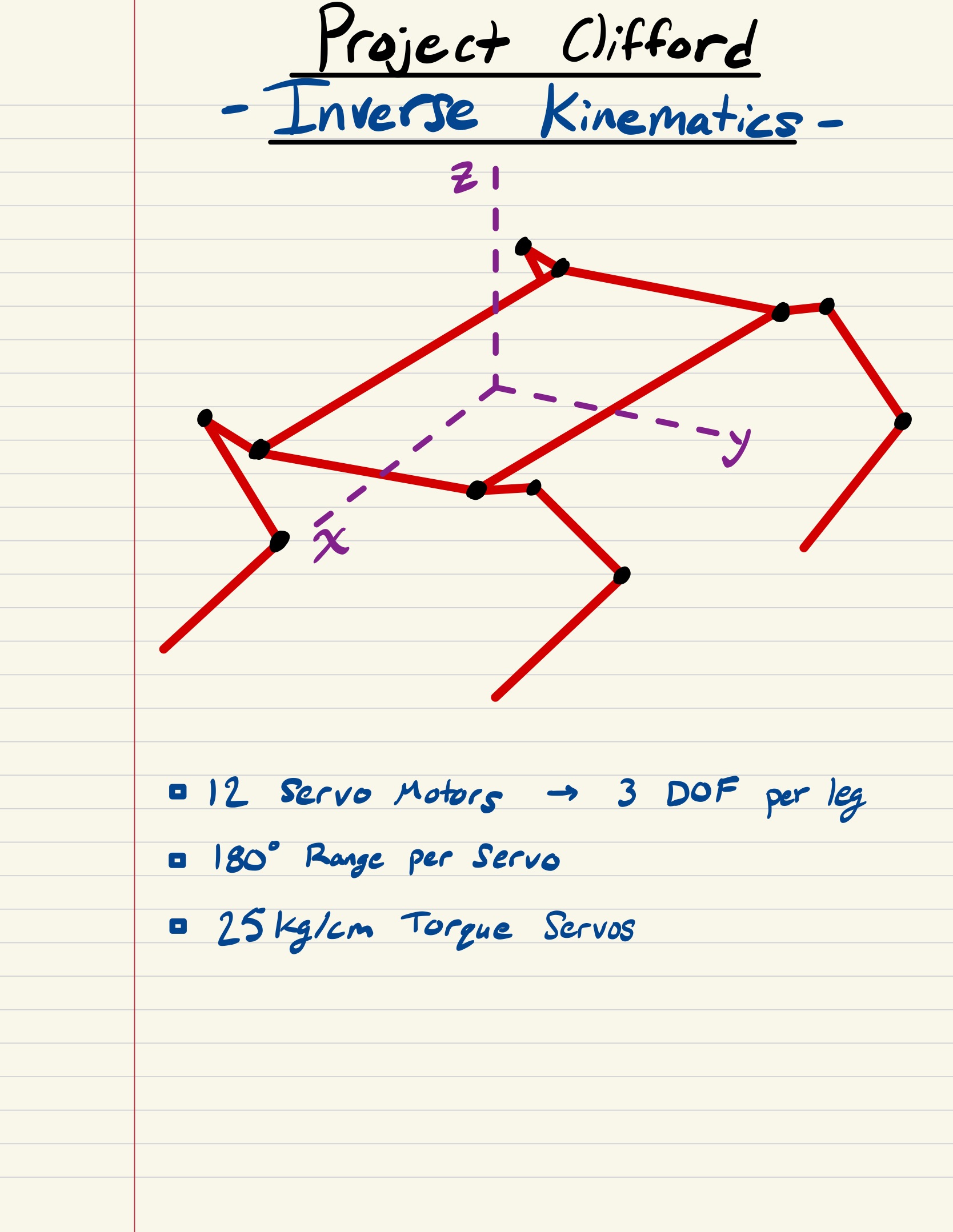
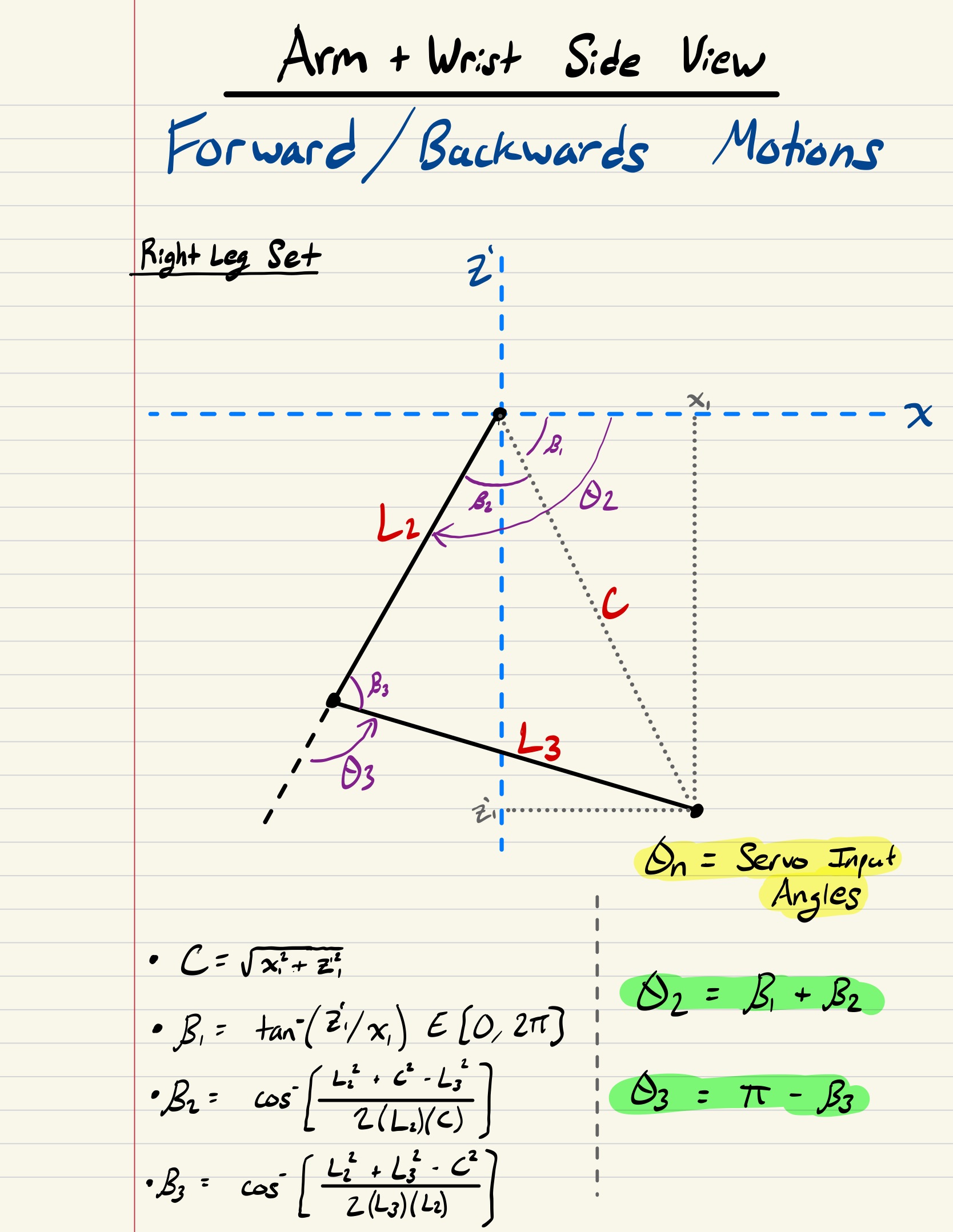
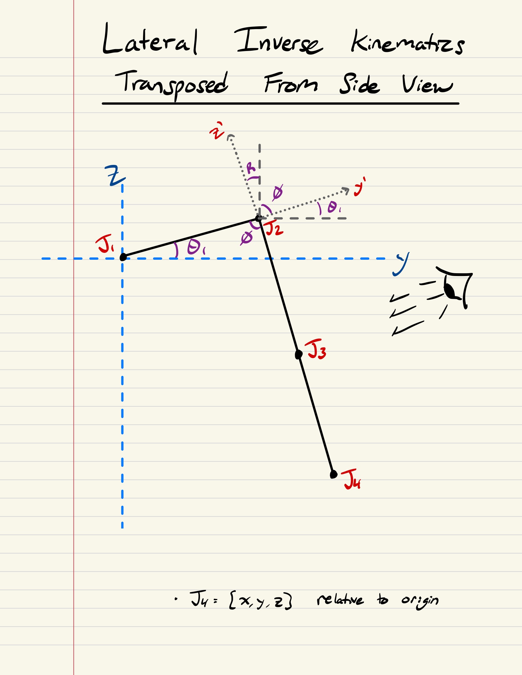
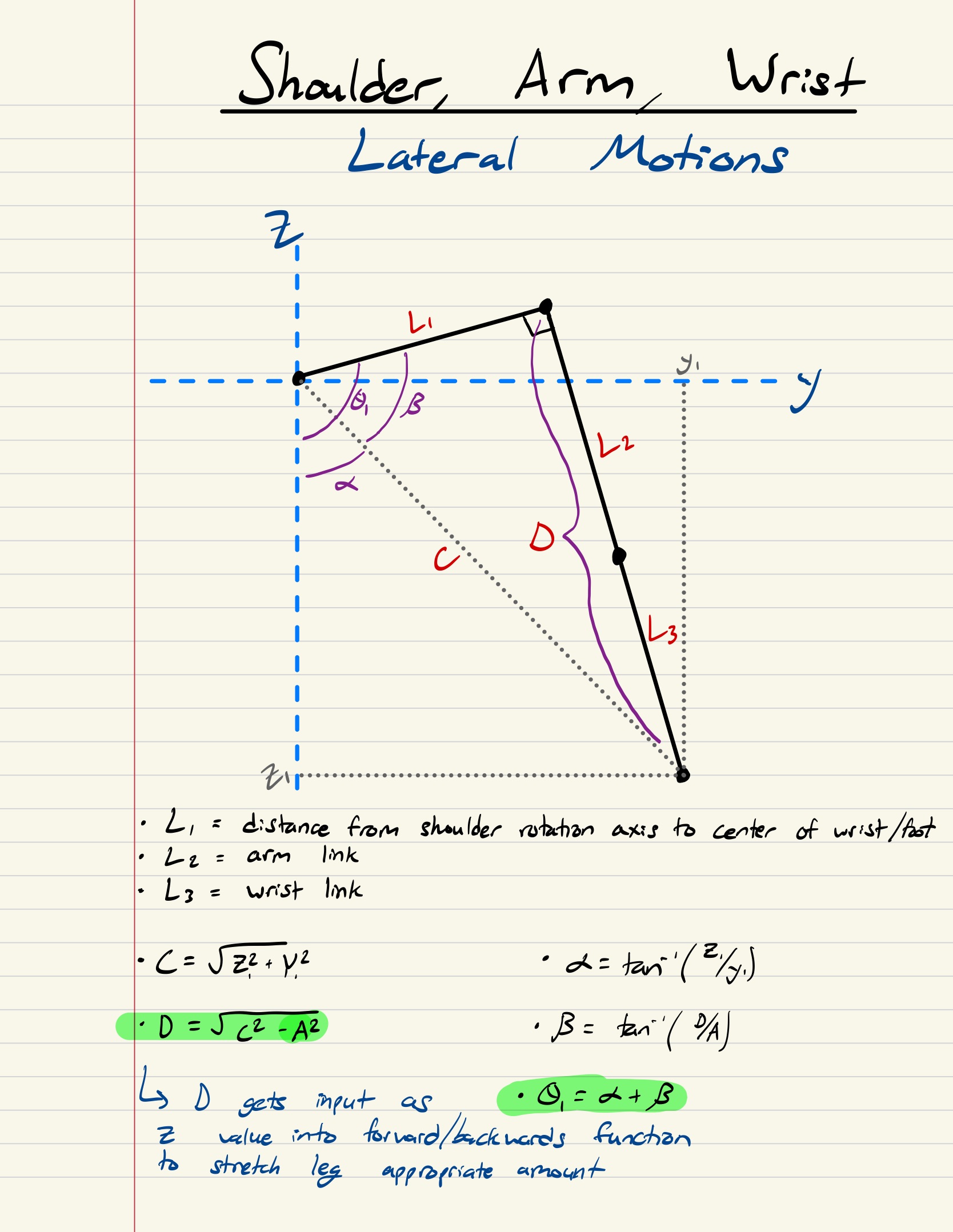
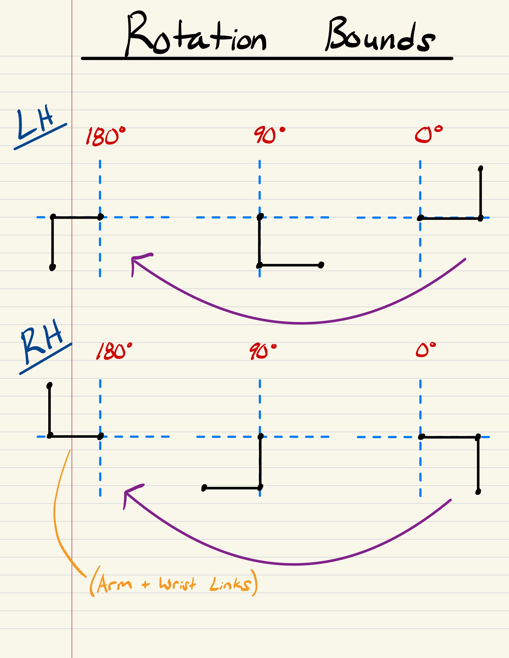
We researched various walking gait patterns and quadruped motion analyses before attempting to model our robot’s movements. The Inverse Kinematics for our robot consists of 2 main analyses - Forward/Backward and Lateral motions. We successfully implemented the Forward/Backward and Lateral inverse kinematics into RViz to help visualize and verify our math without any mechanical or electrical limitations. After verifying the calculations with RViz we slightly modified the inverse kinematics based on the servo rotation limits and how they were physically installed on the robot. For this reason, the calculations for the left and right sides of the robot are mirrored regarding the “arm” and “wrist” servo bounds.
Due to time limitations, we were only able to implement the forward-backward motions onto the physical robot but solved the inverse kinematics for the lateral motions as well and will apply these in the future.
After we programmed the inverse kinematics, we tested different gait designs and optimized the robots foot coordinate positions based its weight distribution. After extensive testing we were able to develop an effective forward and backward walking gait - however improvements can always be made.
Below are the inverse kinematic models we utilized:
 |
 |
 |
 |
 |
References for Inverse Kinematics:
https://www.youtube.com/watch?v=qFE-zuD6jok&t=464s
https://www.youtube.com/watch?v=4rc8N1xuWvc&t=253s
Future Additions
We have several features and functionalities we hope to add in future revisions of Clifford. Our main constraint for this project was a small timeline and for this reason, we were not able to achieve all the features we initially planned.
The main feature we plan to develop is autonomous self-balancing with the gyroscope we already integrated into the system. We planned to implement self balancing in the x and y axis but due to time limitations we were unable to do so. This would improve walking stability and further the real-world application scope of the project.
Another future addition we would like to implement is additional status indicators. We would like to properly develop a ROS node for the LCD and add other status displays the user would be able to toggle between. We would also like to add LED status indicators based on the current mode of the robot.
Bill of Materials
| Component | Quantity | Total Cost |
|---|---|---|
| DS3225MG 25 Kg Servos x2 | 6 | $264 |
| LiPo Battery Charger | 1 | $51 |
| T deans T branch (Parallel) x2 | 1 | $13 |
| Wire Strippers | 1 | $14 |
| 18 Gauge Wire 70 ft | 1 | $20 |
| USB-C Charging cable x2 | 1 | $14 |
| 7.4V 6200mAh Battery | 2 | $60 |
| RPI Heatsink | 1 | $16 |
| HDMI to Micro HDMI | 1 | $14 |
| DROK RPI Buck Converter (used as spare) | 1 | $26 |
| PCA Servo Driver | 2 | $26 |
| RPI 4B | 1 | $100 |
| T Deans Female-Male Adapters | 5 | $13 |
| DROK Servo Buck Converter | 1 | $20 |
| 3D Print Filament | 1 | $25 |
| Micro SD Card | 1 | $13 |
| ELEGOO 3D Printer | 1 | $339 |
| F625zz Ball Bearings | 10 | $18 |
| 3A Buck Converter (for RPI) | 5 | $14 |
| USB-C to Wire | 4 | $14 |
| Spray Paint (Red + Black) | 2 | $28 |
| ADC Board | 1 | $11 |
| M3 Square Nuts | 100 | $11 |
| M4x20mm Bolts | 50 | $14 |
| M4 Square Nuts | 50 | $15 |
| M3x10mm Bolts | 100 | $15 |
References
Special thanks to all these Open-Source Projects!
Other ‘Spot’ projects referenced
https://github.com/mike4192/spotMicro
https://github.com/mangdangroboticsclub/mini_pupper_ros
3D Modelling.
https://www.thingiverse.com/thing:3445283
Raspberry Pi Libraries for LCD
https://github.com/the-raspberry-pi-guy/lcd
Inverse Kinematic Equations
https://www.youtube.com/watch?v=qFE-zuD6jok&t=464s
https://www.youtube.com/watch?v=4rc8N1xuWvc&t=253s
Other Useful Videos
https://www.youtube.com/@ArticulatedRobotics/videos (getting started with ROS)
https://www.youtube.com/watch?v=Cr1ZshV-gqw&t=164s (Designing the walking gait)